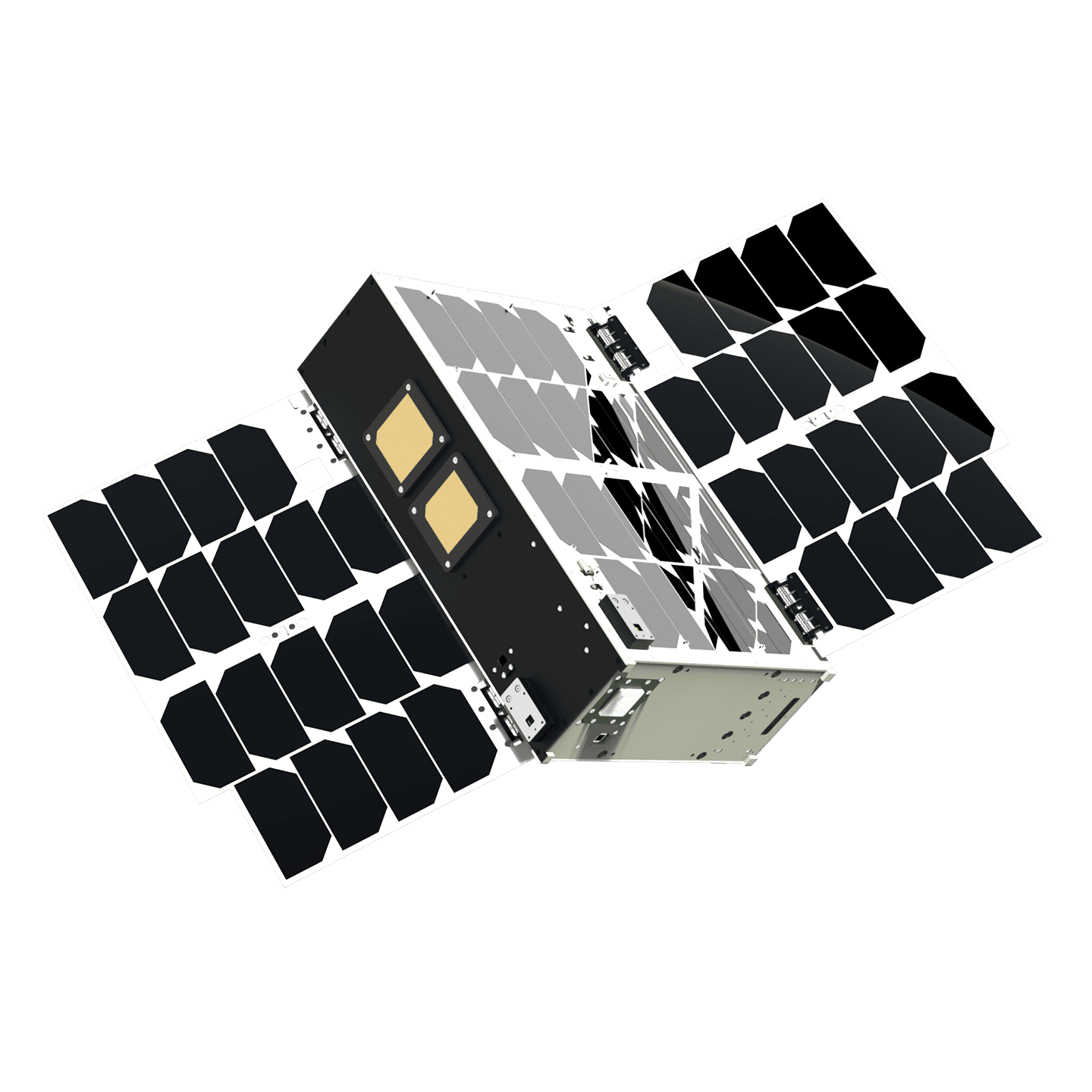
6U Satellite
A dependable and high-performance 6U CubeSat, offering multiple platform enhancements. Space Inventor's advanced 6U satellite offers secure and tactical communication between Earth and space, built for a 10-year mission life.
Mission example
- Safe navigation in regions prone to ice by providing ice reports
MSRP From
*€650.000
Specifications
Description
A dependable and high-performance 6U CubeSat, offering multiple platform enhancements. Space Inventor's advanced 6U satellite offers secure and tactical communication between Earth and space, built for a 10-year mission life. Featuring AES-256 encryption and multiple access protections, it ensures secure connections. This versatile satellite includes customizable subsystems with radiation and EMI shielding, and deployable solar panels for optimal power.
Space Inventor's advanced 6U satellite offers secure and tactical communication between Earth and space, built for a 10-year mission life. Featuring AES-256 encryption and multiple access protections, it ensures secure connections. This versatile satellite includes customizable subsystems with radiation and EMI shielding, and deployable solar panels for optimal power.
It's designed for flexibility, with up to 4 units of payload volume, supporting third-party payloads for diverse missions. Our continuous enhancements in avionics and platform designs promise reliability and technical excellence. This compact, yet capable satellite platform is your gateway to advanced, space-based communication, blending defense-grade security with commercial and scientific capabilities.
*Platform without NRE, Propulsion and Payload
Features
Mechanical drawing

Available modules in satellite

Reaction Wheel

PATCH1-L-R
L-Band Patch 1 antenna. This antenna design offers simplicity and efficiency, making it suitable for various applications like GPS systems, satellite communication, and remote sensing due to its ability to maintain a stable connection within this frequency range.

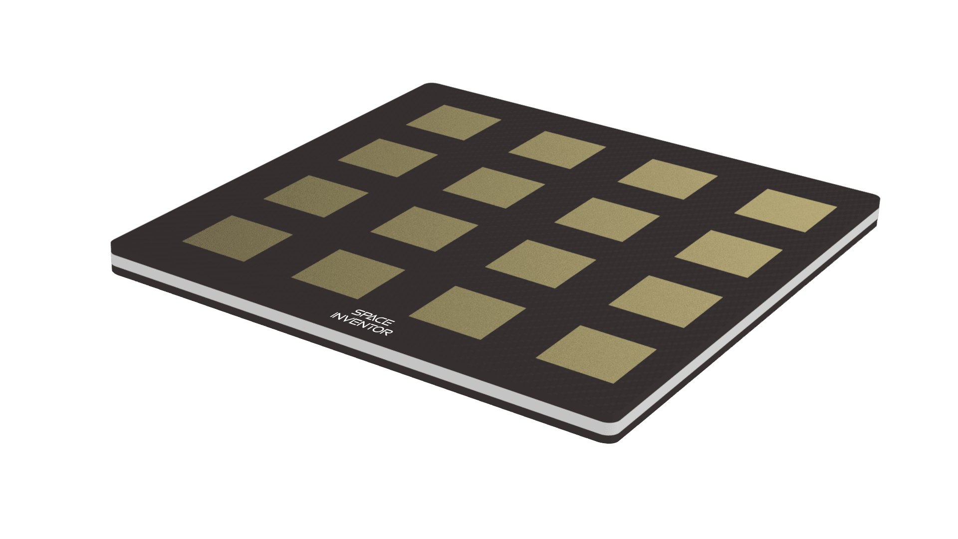
PATCH2X2-S-R
S-Band Patch 2 antenna. An S-band 2x2 antenna array is a compact yet powerful configuration of four antenna elements designed to operate in the S-band frequency range.
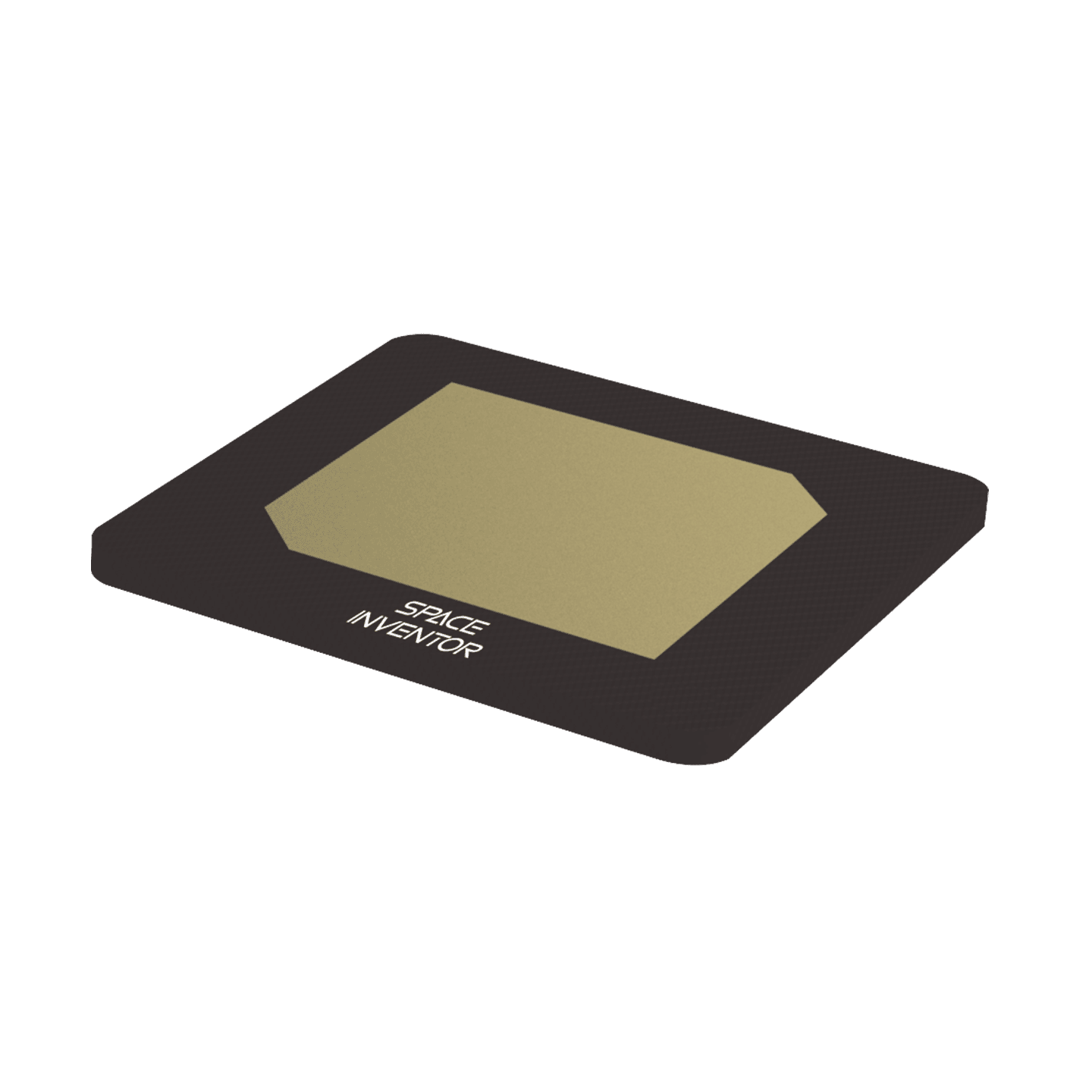
PATCH1-S-R
S-Band Patch 1 antenna. An S-band is widely used in various applications, including satellite communication and radar systems, for its simplicity and effectiveness in this frequency range.
An S-band single patch antenna is a compact single port antenna designed for the 2025-2110 MHz or 2200-2290 MHz S-band frequency range.
PATCH4X4-X-R
X-Band Patch 4 antenna. This configuration provides exceptional performance, making it crucial for advanced radar systems, satellite communication, and high-frequency applications requiring precise directional control and enhanced signal strength.

Battery
Didn’t find what you were looking for?
We’re always ready for a talk about your desires. Please write in detail what you are looking for and we’ll schedule a meeting with you where we can discuss all the details.